
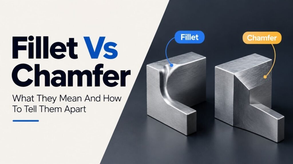
A fillet is a rounded edge that curves smoothly from one surface into another. A chamfer is a flat, angled cut that slices off a sharp corner in a straight line instead of a curve. Both are ways to remove a sharp edge from a part, but they look different, they get made in different ways, and they get chosen for different reasons.
Engineers, machinists, CAD users, and 3D printing hobbyists run into this comparison constantly. The two words sound like they might mean the same thing, and in casual conversation people sometimes use them loosely. But once you can see the difference, you will spot it everywhere: on your phone case, on a door frame, on a bolt hole, on the corner of a table.
Fillet Vs Chamfer: The Simple Definition
Here is the short version before anything else.
A fillet is a rounded transition. Picture two flat surfaces meeting at a corner, then imagine that corner replaced with a smooth curve. That curve is the fillet. In cross-section, a fillet looks like an arc.
A chamfer is a flat transition set at an angle, most often 45 degrees. Instead of curving the corner away, you slice it off in a straight line. In cross-section, a chamfer looks like a short straight line connecting the two original faces, similar to the hypotenuse of a triangle.
| Feature | Fillet | Chamfer |
| Shape | Curved (rounded) | Flat (angled) |
| Cross-section | Arc | Straight line |
| Common angle or size | Defined by a radius | Usually 45°, defined by distance or distance and angle |
| Feel to the touch | Smooth, no edge | Still has two lower-angle edges |
| Typical tool | Ball-end mill, fillet tool, rounding bit | Chamfer mill, chamfer bit, single-point cutter |
Both features exist to solve the same basic problem: a 90-degree corner is sharp, and sharp corners cause trouble. They cut hands, they concentrate stress, they chip during machining, and they catch on things during assembly. A fillet and a chamfer are two different tools for solving that one problem.
See More: Spicy Vs Hot
Fillet Meaning In Engineering And Design
In manufacturing, a fillet is a rounded corner or edge that blends two intersecting surfaces together instead of letting them meet at a sharp point. According to the McGraw-Hill Dictionary of Engineering, a fillet is a concave transition surface between two otherwise intersecting surfaces, sometimes described as a corner piece at the junction of perpendicular surfaces used to lessen the danger of cracks.
Fillets can sit on the inside of a corner or the outside of a corner.
- Interior (concave) fillet: curves inward, like the rounded corner where a wall meets a floor.
- Exterior (convex) fillet: curves outward, like the rounded edge of a smartphone or a bar of soap.
A fillet is defined by its radius. A larger radius means a gentler, wider curve. A smaller radius means a tighter curve that is closer to the original sharp edge.
💡 Tip: If you have ever run your thumb along the rounded edge of a laptop or a kitchen counter and felt no seam at all, that smooth curve is a fillet.
Why Fillets Matter
Fillets are not just there to look nice, although they often do improve appearance. Their main engineering job is to manage stress.
- Stress reduction: Sharp interior corners are natural stress concentration points. A crack is far more likely to start at a sharp 90-degree corner than at a rounded one. A fillet spreads that stress across a wider area, which lowers the chance of cracking or fatigue failure over time.
- Improved flow: In pipes, ducts, and molds, fillets help liquids, gases, or molten material move around a corner more smoothly instead of creating turbulence or trapped pockets.
- Safety: A rounded edge is less likely to cut skin than a sharp one, which is why so many consumer products use fillets on exposed edges.
- Casting and molding quality: In cast or molded parts, sharp internal corners can cause weak spots or defects as the material cools and shrinks. A fillet radius here is often treated as a standard design allowance rather than an optional extra.
Chamfer Meaning In Engineering And Design
A chamfer is a flat surface that replaces a sharp corner with a sloped, angled edge instead of a curve. The Cambridge Dictionary describes a chamfer as a cut on the edge or corner of something that makes it slope slightly rather than staying perfectly square. As a verb, to chamfer a part means to bevel that sharp edge during machining.
A chamfer is usually described by two numbers:
- Distance: how far the cut goes back from the original edge.
- Angle: how steep the cut is, most commonly 45 degrees, though other angles are possible.
Some CAD tools instead ask for two distances, one on each face meeting the corner, which produces the same angled flat.
Chamfers, like fillets, can be internal (concave) or external (convex), and you will often see the term applied to holes as well as outside edges. A chamfered hole has its opening widened slightly at an angle, which is extremely common on bolt holes and pilot holes.
Why Chamfers Matter
- Assembly guidance: A chamfered edge on a shaft, pin, or bolt hole acts like a funnel. It nudges a mating part into alignment instead of forcing an installer to line up two perfectly flat surfaces by hand.
- Burr removal: Machining almost always leaves small rough edges called burrs. A quick chamfer pass removes them cleanly.
- Faster, cheaper machining: A chamfer can usually be cut with a single straight pass of a standard tool. A fillet often needs a rounded tool or a more complex toolpath, which takes more time and can cost more.
- Tool protection: In machining, a chamfered lead-in edge helps guide cutting tools into a part and reduces the risk of chipping the tool or the material at the very start of a cut.
- A more finished look: A chamfer softens a sharp edge without fully rounding it, which is why you see chamfers on furniture edges, door frames, and baseboards.
Types of Fillets
Not every fillet is the same shape or serves the same purpose. CAD software and machining practice recognize a few common variations.
- Constant radius fillet: the most common type. The radius stays the same size along the entire length of the edge, producing a uniform curve from start to finish.
- Variable radius fillet: the radius changes along the edge, often starting small at one end and growing larger at the other. Designers use this when a smooth transition needs to blend into differently sized features, such as where a narrow rib widens into a broader wall.
- Full round fillet: instead of blending two surfaces with a curve of a chosen radius, a full round fillet replaces an entire middle face with a rounded surface tangent to the two side faces. This is common where a raised feature, like a rib or a boss, needs to taper into a smooth dome rather than a defined curve.
- Face fillet: blends two selected faces together directly, even if those faces are not adjacent edges in the model, which gives designers more control over complex organic shapes.
Each of these serves the same underlying goal as a basic fillet: remove a sharp transition and manage how stress or material flows across a surface. The choice between them usually comes down to how complex the surrounding geometry is, not a difference in purpose.
Types Of Chamfers
Chamfers also come in a few recognized variations, mostly differing in how the cut is measured rather than what it looks like.
- Distance-distance chamfer: the most common type in CAD software. You set one distance on each of the two faces meeting at the edge, and the software connects those two points with a flat cut. If both distances are equal, the result is a symmetrical 45-degree chamfer on a right-angle corner.
- Distance-angle chamfer: you set one distance along a face and an angle measured from that face, rather than two separate distances. This is useful when a specific angle matters more than a specific size on each side, such as matching an angle required by a mating part.
- Vertex chamfer: instead of cutting along an edge, some CAD tools let you chamfer a single 3D corner point (a vertex) where three or more edges meet, producing a small flat triangular face at the corner.
- Edge chamfer vs. corner chamfer: in casual shop language, “edge chamfer” usually refers to the long run of a chamfer along a straight edge, while “corner chamfer” refers to the small chamfer where two chamfered edges intersect at a corner. Both are the same feature applied to different parts of a part’s geometry.
As with fillets, these variations do not change the core purpose of a chamfer. They simply give a designer more precise control over exactly where and how the flat angled cut is placed.
Materials And Industries: Where Fillets And Chamfers Show Up
The fillet vs chamfer decision is not limited to one industry. The same two features appear across very different fields, though the reasoning behind choosing one or the other stays consistent.
| Industry | Typical fillet use | Typical chamfer use |
| Automotive | Rounded stress points on structural brackets and suspension components | Chamfered bolt holes and shaft ends for faster assembly |
| Aerospace | Fillets at wing-to-fuselage joints and load-bearing frame corners to resist fatigue cracking | Chamfered fastener holes to reduce weight while keeping assembly precision |
| Consumer electronics | Rounded corners and edges on phone bodies, laptops, and enclosures for comfort and appearance | Chamfered edges on internal brackets or connectors for a crisp, defined line |
| Furniture and woodworking | Rounded edges on tabletops and chair arms for comfort and safety | Chamfered edges on shelves and cabinet fronts for a clean, angular look |
| Construction and architecture | Rounded corners on concrete forms to reduce cracking at corners | Chamfered edges on columns, beams, and baseboards for a finished appearance |
| Plastic injection molding | Fillets on internal corners to prevent stress cracking and improve material flow during molding | Chamfers on part edges to ease ejection from the mold and improve fit |
| Casting (metal) | Fillet radii built into mold cavities to reduce shrinkage cracks at corners | Chamfers on parting lines and mating surfaces to reduce flash and aid fit-up |
This pattern repeats across nearly every manufactured product: fillets protect against stress and improve comfort, while chamfers protect against damage during handling, guide assembly, and finish an edge quickly.
Fillet Vs Chamfer: Key Differences
Once both definitions are clear, the differences fall into a few practical categories.
1. Shape
A fillet is curved. A chamfer is flat and angled. This is the difference you can see and feel immediately.
2. How They Are Made
Fillets typically require a rounded cutting tool, such as a ball-end mill, or a dedicated fillet operation in CAD software. Chamfers can usually be made with a simple angled cutter in a single pass, which tends to make them quicker and less expensive to produce, especially in high-volume manufacturing.
3. Stress Distribution
This is one of the most important engineering differences.
- A fillet spreads stress across a curved surface, which is why fillets are the preferred choice for load-bearing parts, rotating shafts, structural brackets, and any location where fatigue cracking is a real risk.
- A chamfer still leaves two angled transition lines rather than one smooth curve. It does not distribute stress nearly as well, so it is a poor choice for high-stress, load-bearing corners.
4. Cost And Production Speed
Chamfers are generally faster and cheaper to produce because they can be cut with ordinary tools in a single pass. Fillets often need specific tooling and more machine time, although in very high-volume production the cost gap can narrow depending on the process used.
5. Typical Use Case
- Choose a fillet where safety, comfort, stress reduction, or a smooth aesthetic matters most: rounded external corners people will touch, internal corners on load-bearing parts, or any surface where fluid needs to flow smoothly around a bend.
- Choose a chamfer where you need to guide assembly, remove burrs quickly, or create a clean edge without added machining time: bolt holes, shaft ends, mating parts, and edges that need to fit together precisely.
Quick Comparison Table
| Question | Fillet | Chamfer |
| Is the transition curved or flat? | Curved | Flat |
| Best for reducing stress concentration? | Yes | Not as effective |
| Faster and cheaper to machine? | Generally no | Generally yes |
| Common on load-bearing internal corners? | Yes | Less common |
| Common on bolt holes and shaft ends? | Less common | Yes |
| Common on consumer product edges (phones, furniture)? | Yes, for a soft rounded look | Yes, for a crisp angled look |
Understanding Stress Concentration In Plain English
Engineers often mention a “stress concentration factor” when explaining why fillets outperform chamfers on load-bearing corners. This idea is simpler than it sounds.
Imagine pulling on a flat strip of material with a sharp 90-degree notch cut into one side. When you pull, the force does not spread evenly across the whole strip. Instead, it bunches up right at the tip of that sharp notch, the same way water rushing through a wide river suddenly speeds up when it is forced through a narrow gap. That bunching-up effect is stress concentration, and a sharp corner is one of the most common places it happens.
A fillet widens that “gap” gradually. Because the curve transitions slowly from one surface to another, the force has more room to spread out before it reaches the corner, so the peak stress at any single point drops significantly compared to a sharp corner.
A chamfer helps too, since it removes the sharp 90-degree point entirely. But because a chamfer still has two angled transition points instead of one smooth curve, some concentration remains at those transition lines. It is an improvement over a sharp corner, but not as strong an improvement as a well-sized fillet.
This is why aerospace, automotive, and structural engineers default to fillets on any corner expected to carry repeated or high load, and reserve chamfers for edges that are mainly about assembly, safety, or finish rather than long-term structural performance.
Fillet Weld: A Related But Different Term
The phrase “fillet weld” comes up often in searches related to fillets, and it deserves its own short explanation since it works a little differently from a machined fillet.
A fillet weld is a type of weld with a roughly triangular cross-section, used to join two pieces of metal that meet at an angle, most commonly a right angle, such as a plate welded onto the face of another plate. The name comes from the same rounded, corner-filling idea as a machining fillet: metal weld material fills the inside corner where the two pieces meet, smoothing the transition and joining the parts structurally at the same time.
A fillet weld is not something you create with a Fillet command in CAD software. It is a real physical joining process performed with a welding torch or wire, and it is usually represented in engineering drawings using a specific fillet weld symbol placed on a leader line pointing to the joint. The size of a fillet weld is typically called out as the length of the two equal legs of that triangular cross-section, similar to how a fillet radius defines the size of a rounded corner.
While a fillet weld and a machined fillet are different things, they share the same underlying purpose: filling or rounding a sharp interior corner to make the resulting structure stronger and less likely to fail at that corner.
Fillet Vs Chamfer Vs Bevel
A third term often enters this conversation: bevel. Many people use “bevel” and “chamfer” interchangeably, but they are not identical.
A bevel is any sloped edge cut at an angle other than 90 degrees. A chamfer is technically a specific type of bevel, one that is typically cut at exactly 45 degrees and connects two surfaces that would otherwise meet at a right angle. A bevel’s angle can vary more widely and is often used for decorative or structural purposes, such as in welding preparation or picture-frame edges, while a chamfer is more standardized and closely tied to mechanical design and machining.
Put simply:
- Chamfer: usually 45 degrees, functional, common in machining and CAD.
- Bevel: any non-right angle, broader use, common in woodworking, glasswork, and welding.
- Fillet: curved, not angled at all.
⚠️ Common mix-up: Not every angled edge is a chamfer. If the slope is not close to 45 degrees or the context is decorative rather than mechanical, “bevel” is often the more accurate word.
Tools Used To Create Fillets And Chamfers
The tools used to physically cut a fillet or a chamfer differ enough that recognizing them helps explain why one feature costs more time than the other.
Tools for Fillets
- Ball-end mill: a rotary cutting tool with a rounded tip, commonly used in CNC machining to cut a curved fillet into a corner or pocket.
- Fillet router bit / roundover bit: used in woodworking to cut a rounded profile along the edge of a board in a single pass.
- Radius gauge: not a cutting tool, but a measuring tool used to check that a finished fillet matches its specified radius.
Tools for Chamfers
- Chamfer mill: a rotary cutting tool with an angled cutting edge, most often set at 45 degrees, used in CNC machining to cut a flat angled edge quickly.
- Chamfer router bit: the woodworking equivalent of a chamfer mill, commonly available as a 45-degree chamfer router bit for cutting clean angled edges into wood.
- Deburring tool or hand chamfer tool: a simple handheld tool used to knock down sharp edges and small burrs with a light manual chamfer, common in metalworking shops for quick edge finishing.
- Countersink bit: while technically a different feature, a countersink bit cuts a cone-shaped, angled recess similar in concept to a chamfer, usually to let a screw head sit flush with a surface.
Because a chamfer mill or chamfer router bit can usually finish an edge in one straight pass, chamfering tends to be faster on a shop floor than filleting, which often needs a rounded tool moving along a more complex path to keep the curve consistent.
A Note On Named Products
Some product names borrow directly from these engineering terms because they describe a visible design detail. For example, “Oakley Chamfer” refers to a line of sunglasses named for the angled, chamfered detailing along the frame, not to a cutting tool or CAD feature.
When a brand name and an engineering term overlap like this, the product name usually points back to the same core meaning of chamfer described throughout this article: a flat, angled edge rather than a rounded one.
Fillet Vs Chamfer In CAD
Almost every CAD program includes dedicated tools for both features, and the commands tend to work in a similar way across platforms, even though the exact names and menus differ.
Fillet Vs Chamfer In AutoCAD
In AutoCAD, FILLET rounds the corner between two lines, arcs, or polyline segments once you set a radius. CHAMFER replaces a corner with a flat angled edge once you set either two distances or a distance and an angle. Both commands work on 2D geometry; for 3D solids, AutoCAD uses the related FILLETEDGE and CHAMFEREDGE commands, which apply the same logic to solid model edges instead of flat lines.
A typical AutoCAD chamfer workflow looks like this:
- Start the CHAMFER command.
- Type “D” to set distances, or “A” to set an angle instead.
- Enter the first and second chamfer distances (or distance and angle).
- Select the first line, then the second line.
- AutoCAD trims or extends the lines automatically and adds the angled edge.
The FILLET command follows a similar pattern, except you set a radius instead of a distance, and the corner becomes a smooth arc rather than a flat cut.
Fillet Vs Chamfer In SolidWorks
In SolidWorks, both features are available as sketch tools and as solid modeling features. The Fillet feature rounds a selected edge or face using a chosen radius. The Chamfer feature can be defined a few different ways, most commonly by an angle and a distance, or by two distances, letting you control exactly how the flat cut is oriented relative to the original edges.
Because SolidWorks is feature-based, fillets and chamfers appear in the model history tree, which makes it easy to edit the radius or distance later without rebuilding the whole part.
Fillet Vs Chamfer In Fusion 360 And Other CAD Tools
Fusion 360, Onshape, and similar parametric CAD tools follow the same basic idea: select an edge, choose Fillet or Chamfer from the Modify menu, and set a radius for a fillet or a distance and angle for a chamfer. Some of these tools also support more advanced variations, like variable-radius fillets that change size along an edge, or chamfers defined by two different distances on each face for an asymmetric cut.
In Fusion 360, the Fillet tool sits under the Modify panel and offers constant, chord-length, and variable-radius options directly in one dialog box, so a designer can switch between them without starting a new feature. The Chamfer tool in the same panel offers equal-distance, two-distance, and distance-angle modes, matching the same core options found in SolidWorks and AutoCAD.
Onshape works very similarly, with Fillet and Chamfer listed as separate feature tools in the toolbar. Because Onshape is fully cloud-based and built around a parametric feature tree, edits to a fillet radius or chamfer distance automatically ripple through the rest of the model, the same way they do in SolidWorks and Fusion 360.
FreeCAD, a free and open-source CAD package, includes Fillet and Chamfer as dedicated Part Design tools as well, using the same radius-for-fillet and distance-or-angle-for-chamfer logic. The terminology and workflow stay consistent across nearly all mainstream parametric CAD software, which is part of why the fillet vs chamfer distinction is considered a foundational CAD skill rather than a program-specific quirk.
See More: Traveling vs Travelling
A Quick Reference For CAD Fillet And Chamfer Inputs
| Software | Fillet input | Chamfer input |
| AutoCAD | Radius | Distance, or distance and angle |
| SolidWorks | Radius (constant, variable, or face fillet) | Angle-distance, or two distances |
| Fusion 360 | Constant, chord-length, or variable radius | Equal distance, two distance, or distance-angle |
| Onshape | Radius | Distance, or distance and angle |
| FreeCAD | Radius | Distance, or distance and angle |
Even though the menu names differ slightly, every one of these programs is asking for the same two pieces of information at heart: how big should the curve be, or how far and how steep should the flat cut be.
Fillet Vs Chamfer In 3D Printing
Fused deposition modeling (FDM) printers build parts layer by layer, and this changes which edge treatment works best compared to traditional machining.
The core issue is overhang angle. Most FDM printers can reliably print an overhang of around 45 degrees without support material, and many can push a bit further depending on the printer and settings. A fillet, however, starts at 0 degrees from horizontal right where it meets a flat base, because the very bottom of a curve is momentarily flat. That means a standard fillet sitting right on the print bed often needs support material to print cleanly, while a 45-degree chamfer in the same spot usually prints fine without any support at all.
This leads to a simple rule that many designers follow for 3D printed parts.
| Situation | Better choice | Why |
| Bottom edge that touches the print bed | Chamfer | Avoids the near-zero-degree overhang a fillet creates at the base |
| Internal corner under mechanical stress | Fillet | Spreads stress better, less likely to crack |
| Lead-in for a screw or press-fit pin | Chamfer | Easier to model, easier to print, guides assembly |
| External corner meant to feel smooth in the hand | Fillet | Rounded feel with no sharp transition |
| Vertical edge running straight up the part | Either works well | No overhang concern on a vertical edge |
Some designers use a hybrid trick sometimes called a “chamfillet”: a chamfer that blends into a fillet partway up an edge, giving a printable overhang near the bed while keeping a rounded look higher up. This is a workaround built specifically for the constraints of layer-based printing rather than a term you will see in traditional machining.
💡 Tip: If a slicer preview shows unexpected support structures under a rounded edge, check whether that edge is a fillet sitting directly on the build plate. Switching it to a 45-degree chamfer, at least for the first few millimeters, often solves the problem.
Fillet Vs Chamfer Across Different 3D Printing Processes
The fillet vs chamfer tradeoff described above applies most directly to FDM printing, where material is extruded layer by layer and overhangs are a real physical constraint. Other 3D printing processes behave differently.
- Resin printing (SLA and DLP): overhang limits are usually less strict than FDM, because resin cures in thin, precise layers under a light source rather than being pushed out of a nozzle. Fillets tend to print more successfully on resin printers, though very sharp internal fillets can still trap uncured resin if they are too tight to drain properly.
- Selective laser sintering (SLS): parts are supported by surrounding unsintered powder during the entire print, so overhang angle is not a major concern. Fillets and chamfers can largely be chosen based on strength and appearance alone, similar to traditional machining.
- Metal 3D printing (DMLS and similar): overhang limits return as a real concern, similar to FDM, along with added residual stress from the printing process itself. Fillets are often preferred on load-bearing internal corners specifically because metal printed parts already carry higher risk of stress cracking at sharp transitions.
This is a useful reminder that “fillet vs chamfer” is not a single universal rule. The right choice always depends on the manufacturing process being used, not just the geometry of the part.
How To Decide Between A Fillet And A Chamfer
When a corner does not obviously call for one or the other, a short checklist can help.
- Does this corner carry load or repeated stress? If yes, lean toward a fillet. Rounded transitions distribute stress far better than flat angled ones.
- Does this edge need to guide a mating part into place? If yes, lean toward a chamfer. The angled taper naturally funnels one part into another.
- Will a person touch or hold this edge often? If yes, a fillet usually feels safer and more comfortable, though a light chamfer can also remove sharpness with less material change.
- Is this edge sitting on a 3D printer’s build plate? If yes, a chamfer usually avoids unwanted support material better than a fillet.
- Is production cost or machining time the biggest constraint? If yes, a chamfer is typically quicker and cheaper to produce.
- Does the design need a soft, rounded, “finished” appearance, like a consumer product? If yes, a fillet often looks more polished.
- Does the design need a crisp, defined, angular appearance? If yes, a chamfer usually reads as more precise and technical.
Most real designs use both features in different places on the same part. A single bracket might have filleted internal corners to resist cracking, a chamfered bolt hole to guide a fastener, and a chamfered outer edge to remove burrs from the final cut.
How To Pronounce Fillet And Chamfer
Pronunciation causes real confusion here, mostly because “fillet” has two accepted pronunciations depending on context and region.
- Fillet (engineering sense): pronounced “FIL-it,” with a clear “t” sound at the end, rhyming with “billet.” This is the standard pronunciation used in machining, CAD, and manufacturing across American and British English.
- Fillet (food sense): in American English, a cut of meat or fish is also usually pronounced “FIL-it.” In British English and in French-influenced cooking contexts, the same word is often pronounced “fi-LAY,” with a silent “t,” borrowed from the original French spelling “filet.”
- Chamfer: pronounced “CHAM-fer,” with the same “cham” sound as in “champion” and a soft “fer” ending. There is no widely used alternate pronunciation in engineering contexts.
⚠️ Common mistake: Do not pronounce the engineering “fillet” as “fi-LAY.” In machining, CAD, and manufacturing, “FIL-it” is the standard and expected pronunciation, even though the culinary word spelled the same way is often said differently.
British Vs American Usage
The engineering meaning of “fillet” is used consistently in both American and British technical writing, and the “FIL-it” pronunciation is standard in both regions when the word refers to an edge or corner treatment. The split shows up almost entirely in the food sense of the word.
- In American English, both the food cut and the engineering feature are commonly pronounced “FIL-it.”
- In British English, the food cut is very often pronounced “fi-LAY,” closer to the original French, while the engineering feature is still pronounced “FIL-it.”
“Chamfer” does not show a strong regional split. American and British engineers, machinists, and CAD users generally use the same “CHAM-fer” pronunciation and the same core meaning.
Synonyms And Related Words
A few words overlap with fillet and chamfer in meaning, but each carries its own shade of difference worth knowing.
| Word | Meaning | How it differs from fillet or chamfer |
| Round | A general term for a rounded edge, often external | Functionally similar to a fillet; some machinists reserve “fillet” strictly for internal corners and “round” for external ones |
| Radius | The measurement defining a fillet’s curve size | Not a feature by itself, but the value that describes one |
| Bevel | Any sloped edge cut at a non-right angle | Broader than “chamfer,” which is typically a specific 45-degree cut |
| Roundover | A rounded edge cut with a roundover router bit | A woodworking-specific term, functionally close to a fillet |
| Countersink | A cone-shaped recess cut around a hole, usually to seat a screw head flush | Shares the angled-cut idea with a chamfer, but is deeper and shaped to fit a specific fastener head rather than simply softening an edge |
| Deburr | The general process of removing burrs from a machined edge | A chamfer is one common method used to deburr a part, but deburring can also be done with other tools that do not create a defined chamfer angle |
None of these words are true substitutes for “fillet” or “chamfer.” Each describes a related but distinct concept, and mixing them up in a technical drawing or a CAD file can lead to real manufacturing confusion, since a machinist reading a callout needs to know exactly which feature to cut.
Word Origin And Grammar Notes
Origin
Fillet comes from the Old French word “filet,” a diminutive of “fil,” meaning thread or string. The original sense referred to a thin strip or band, which is also where the culinary meaning (a thin strip of meat or fish) comes from. The engineering sense grew out of the same idea of a thin band or strip, applied here to a narrow rounded transition between surfaces.
Chamfer comes from the Old French phrase “chanfrain” or “chanfraindre,” related to cutting or breaking an edge at an angle. Over time this shortened into “chamfer” in English, keeping its meaning tied to cutting off a sharp corner.
Part of Speech
Both words work as nouns and verbs.
- As a noun: “The part has a small fillet where the two surfaces meet.” / “Add a chamfer to the bolt hole.”
- As a verb: “We filleted the inside corner to reduce stress.” / “The machinist chamfered the edge before assembly.”
The past tense forms are “filleted” and “chamfered.” The present participle forms are “filleting” and “chamfering.”
Fillet Vs Chamfer Vs Radius Vs Round
A few related terms show up alongside fillet and chamfer, and it helps to separate them clearly.
- Radius is not a separate edge treatment. It is the measurement that defines how large a fillet’s curve is. Saying “add a 3 mm radius” and “add a 3 mm fillet” usually mean the same practical thing in a design conversation.
- Round is sometimes used interchangeably with “fillet,” especially for external, convex curves. Some machinists reserve “fillet” specifically for internal (concave) corners and “round” for external (convex) ones, though general usage often blends the two.
- Roundover is a woodworking term for a rounded edge cut with a roundover router bit, functionally very similar to a fillet, but the word is specific to woodworking rather than metal machining or CAD.
Other Meanings Of Fillet
Because “fillet” is such a common food word, it is worth separating that meaning clearly from the engineering one, since a search for “fillet” alone often mixes both.
- Culinary fillet: a boneless strip or piece of meat or fish, such as a salmon fillet, a chicken fillet, or a fillet steak. This meaning has nothing to do with edges or angles; it refers to a cut of food.
- Fillet knife: a thin, flexible knife used to cut fillets from fish, unrelated to any cutting tool used in machining.
- Fillet weld: this one does overlap with engineering. A fillet weld is a weld with a roughly triangular cross-section that joins two surfaces meeting at an angle, commonly a right angle. The name comes from the same rounded-corner idea as a machining fillet, even though a fillet weld is a joining method rather than an edge treatment.
If a search result or conversation suddenly shifts from CAD software to cooking, this is almost always the reason: the same word, two unrelated meanings.
Worked Examples
Reading definitions is one thing; seeing the choice applied to real parts makes it click faster.
Example 1: A metal bracket that holds a shelf. The inside corner where the vertical and horizontal arms of the bracket meet carries the full weight of the shelf and anything placed on it. This corner gets a fillet, sized with a generous radius, because the load is constant and a crack starting at a sharp inside corner could eventually cause the bracket to fail.
Example 2: A machined shaft that slides into a bearing. The very end of the shaft needs to slide smoothly into the bearing bore without catching on a sharp edge. This end gets a chamfer, because the angled taper acts like a funnel, guiding the shaft into alignment even if it is not perfectly centered when the installer starts pushing it in.
Example 3: A 3D printed enclosure with a rounded look. The design brief calls for smooth, rounded corners on the outside of the case for a modern appearance. Where those rounded edges meet the bottom of the case, sitting flat on the print bed, the designer switches to a 45-degree chamfer for the first couple of millimeters, then blends it into the full fillet higher up, avoiding support material while still keeping most of the rounded look.
Example 4: A wooden tabletop. The edge of the tabletop needs to be safe to lean against and pleasant to touch. A woodworker uses a roundover router bit to cut a fillet-style rounded edge, prioritizing comfort and a soft appearance over machining speed.
Example 5: A stamped sheet metal panel with punched holes. Each punched hole needs a fastener to pass through smoothly during assembly on a factory line. The edges of these holes get a light chamfer, since workers are installing many fasteners quickly and any small taper that helps guide a screw in saves real time across thousands of units.
Common Mistakes With Fillet And Chamfer
❌ Incorrect: “We chamfered the corner to reduce stress on the load-bearing bracket.”
✅ Correct: “We filleted the corner to reduce stress on the load-bearing bracket.”
Why: Chamfers do not distribute stress as effectively as fillets, so a high-stress structural corner calls for a fillet, not a chamfer.
❌ Incorrect: “The bolt hole has a fillet to help guide the bolt into place.”
✅ Correct: “The bolt hole has a chamfer to help guide the bolt into place.”
Why: The angled, funnel-like shape of a chamfer is what makes it useful for guiding assembly. A rounded fillet does not create the same guiding taper.
❌ Incorrect: Using “chamfer” and “bevel” as if they always mean the exact same angle.
✅ Correct: Using “chamfer” for a roughly 45-degree cut on a right-angle corner, and “bevel” for a more general sloped edge at other angles.
Why: A chamfer is a specific, standardized type of bevel, not a universal synonym for every angled cut.
❌ Incorrect: “Add a fillet to the bottom edge of the 3D printed part so it prints without any extra work.”
✅ Correct: “Add a chamfer to the bottom edge of the 3D printed part so it prints without needing support material.”
Why: A fillet touching the print bed creates a near-zero-degree overhang at its base, which most FDM printers cannot bridge cleanly without support, while a 45-degree chamfer usually prints without any support at all.
❌ Incorrect: Assuming “radius” is a separate feature you add alongside a fillet.
✅ Correct: Understanding that radius is simply the number that defines how large a fillet’s curve is.
Why: Saying “add a fillet” and “specify the radius” are two parts of the same instruction, not two different features.
❌ Incorrect: Calling every angled cut on a piece of wood or metal a “chamfer.”
✅ Correct: Reserving “chamfer” for a roughly 45-degree cut on a right-angle corner, and using “bevel” for other sloped edges, especially deeper cuts used in welding preparation or decorative woodworking.
Why: Using the more general “bevel” for anything that is not a standard 45-degree corner cut keeps technical drawings and conversations accurate.
See More: Creater or Creator
Frequently Asked Questions
What does fillet mean in engineering?
A fillet is a rounded transition between two surfaces that would otherwise meet at a sharp corner. It can be concave (internal) or convex (external) and is defined by a radius.
What does chamfer mean in engineering?
A chamfer is a flat, angled cut that replaces a sharp corner with a sloped surface, typically at 45 degrees. It is defined by a distance, or by a distance and an angle.
Is a fillet stronger than a chamfer?
A fillet generally distributes stress more evenly than a chamfer, which is why fillets are preferred for load-bearing corners and parts subject to fatigue. A chamfer is not as effective at reducing stress concentration.
Which is cheaper to machine, a fillet or a chamfer?
Chamfers are usually quicker and cheaper to machine because they can be cut with a single-pass angled tool. Fillets often require rounded tooling or more complex toolpaths, which can add time and cost.
Should I use a fillet or a chamfer for 3D printing?
For edges that sit directly on the print bed, a chamfer around 45 degrees usually prints without support, while a fillet in the same spot often needs support material. For internal corners under stress, a fillet is still the better structural choice.
Is a chamfer the same as a bevel?
A chamfer is a specific type of bevel, typically cut at 45 degrees to remove a right-angle corner. Bevel is the broader term for any sloped edge cut at an angle other than 90 degrees.
How do you say fillet in engineering?
In engineering, machining, and CAD, “fillet” is pronounced “FIL-it,” with the “t” sound pronounced clearly. This differs from the French-style “fi-LAY” pronunciation sometimes used for the culinary cut of meat or fish.
Do SolidWorks and AutoCAD use the same fillet and chamfer commands?
The underlying concept is the same in both programs, but the exact commands differ. AutoCAD uses FILLET and CHAMFER for 2D geometry and FILLETEDGE and CHAMFEREDGE for 3D solids. SolidWorks uses dedicated Fillet and Chamfer features, available in both sketch mode and solid modeling.
Can an edge have both a fillet and a chamfer?
Yes. Some designs combine both, especially in 3D printing, where a chamfer is used near the print bed to avoid support material and a fillet is used above it for a smoother look and feel.
What is the difference between fillet and radius?
Radius is not a separate feature; it is the measurement used to define the size of a fillet’s curve. A larger radius creates a wider, gentler fillet, while a smaller radius creates a tighter curve.
Is fillet a noun or a verb?
Fillet works as both. As a noun, it names the rounded transition itself, as in “the part has a fillet at that corner.” As a verb, it describes the action of adding one, as in “we filleted the inside corner.”
What angle is a standard chamfer?
Most standard chamfers are cut at 45 degrees, since this angle evenly splits the two faces of a right-angle corner. Other angles are possible and are typically called out with a distance-and-angle dimension when the design needs something other than 45 degrees.
Why do bolt holes usually have a chamfer instead of a fillet?
A chamfer creates a funnel-like taper at the opening of a hole, which helps guide a bolt, pin, or fastener into alignment during assembly. A rounded fillet does not create the same guiding taper, so chamfers are the more common choice for hole entries.
Does a fillet weld use the same shape as a machined fillet?
Not exactly. A fillet weld has a roughly triangular cross-section formed by weld material filling an interior corner between two welded plates, while a machined fillet is a smooth curved cut. Both share the same underlying purpose of smoothing and strengthening an interior corner, but they are produced in completely different ways.
Final Thoughts
The fillet vs chamfer choice comes down to shape, purpose, and cost. A fillet rounds a corner into a smooth curve, spreads stress evenly, and suits load-bearing or hand-touched edges. A chamfer cuts a flat angled edge, usually at 45 degrees, and suits assembly guidance, burr removal, and faster, cheaper machining.
Neither feature is universally better than the other; they solve different problems. When you are looking at a part, whether on a screen in CAD software or in your hand, ask what that corner needs to do. If it needs to survive repeated stress or feel smooth to the touch, reach for a fillet. If it needs to guide a mating part into place or get finished quickly on the machine, a chamfer is usually the right call.

Abdul Rehman Jutt is the author behind Grammar Wordz, with 4 years of experience researching and writing about English grammar, words, meanings, and language rules. Their goal is to make grammar simple, clear, and easy to understand through accurate and useful explanations.